Linear Valve 3D Printed in Polycarbonte

Getting Quality Results 3D Printing Polycarbonate ( PC )

Polycarbonate is a thermoplastic known for its strength, transparancy and wide ranging thermocompatilbity.  It is also probably the most readily accessible filament that can hold up to sterilization though autoclaving. These properties have lead to wide range use of polycarbonate in industry from things ranging from fighter jet cockpit canopies, bulletproof vests, and compact discs (CDs), as just a few examples.

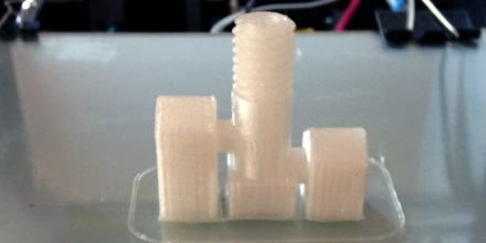
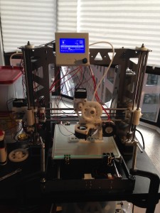
I have been interested in prototyping fluidic parts in polycarbonate for it’s transparency, strength, and possibility for autoclaving. I have autoclaved a few test parts and haven’t seen any problems with deformation. Printing wise, the results I’m getting are starting to be pretty good (bellow), these are square parts from good bed adhesion, that don’t laminate and are somewhat transparent. Here I will share how I’m getting them on my P3Steel.

Linear Valve 3D Printed in Polycarbonte
Linear Valve 3D Printed in Polycarbonate

I looked for guides when I got started with 3D printing a little more than a year ago and found Richrap’s guide. He got results and compares strength characteristics. Tom Sanladerer also has a video about it. I am writing this guide thinking of my knowledge I had before for I started 3D printing with the hope others will find it useful.

Main theme is polycarbonate printing wants heat, heat, and more heat

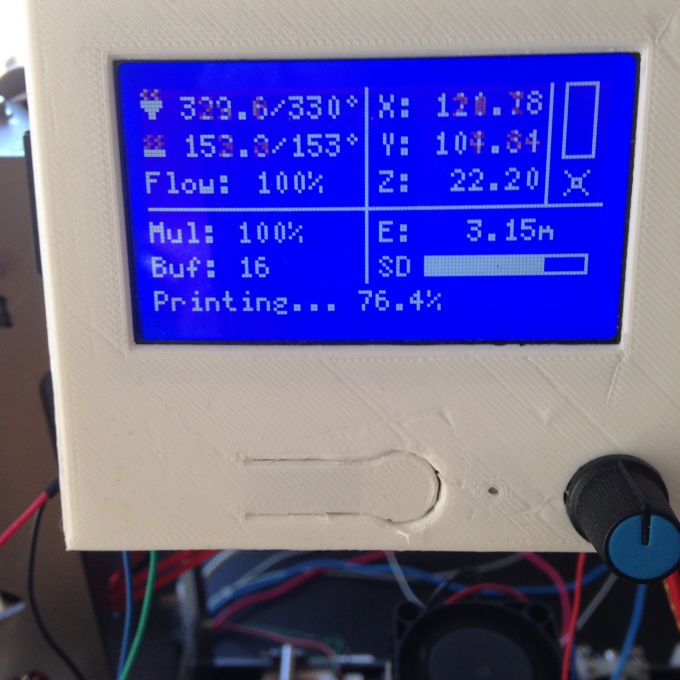
I’ve sourced my Gizmodorks Polycarboante from Amazon.com. There it’s printing temperature is listed at 255-300 C. Guidance is given for keeping the filament dry but no guidance is given on bed temperatures. I’ve been getting my best results with a 330 Deg C hot end and a 153 degrees C on the bed. I’d like to push the hot end temp up even further.

RepRap Display
Repitier display shows bed at 153 deg C and hot end at 330 deg C.

Getting good bed adhesion

I’ve found this stuff likes a very hot bed and and wants to be extruded at high temperature at least by RepRap standards. I’ve been printing onto a 1/8″ glass substrate with the bed temperature at 153 Deg C. It’s not that I started at 153 it’s been a gradual increase of bed temperature to prevent edge curling and for part adhesion. In addition I also brush the bed with Wolf Bite Mega before printing. It’s been a combination of the high bed temperatures and the Wolf Bite that has gotten me to good bed adhesion. These parts come right off too as the bed curls and are easily removed, similar to PEI for ABS, when the bed is cool.

You might say, 153 C on the bed seems a little excessive and or your printer might not be able to hit 153 on the bed. My findings have been filaments stick the a bed best at temperature that is around or slightly above their glass transition temperature. For polycarbonate this is about 150 deg C, perhaps it’s the wolf bite that gets us to the last bit.

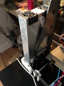
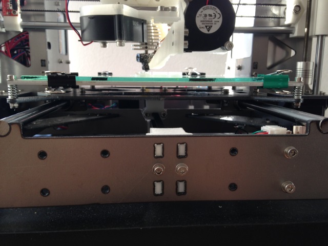
Hitting 153 C on the bed

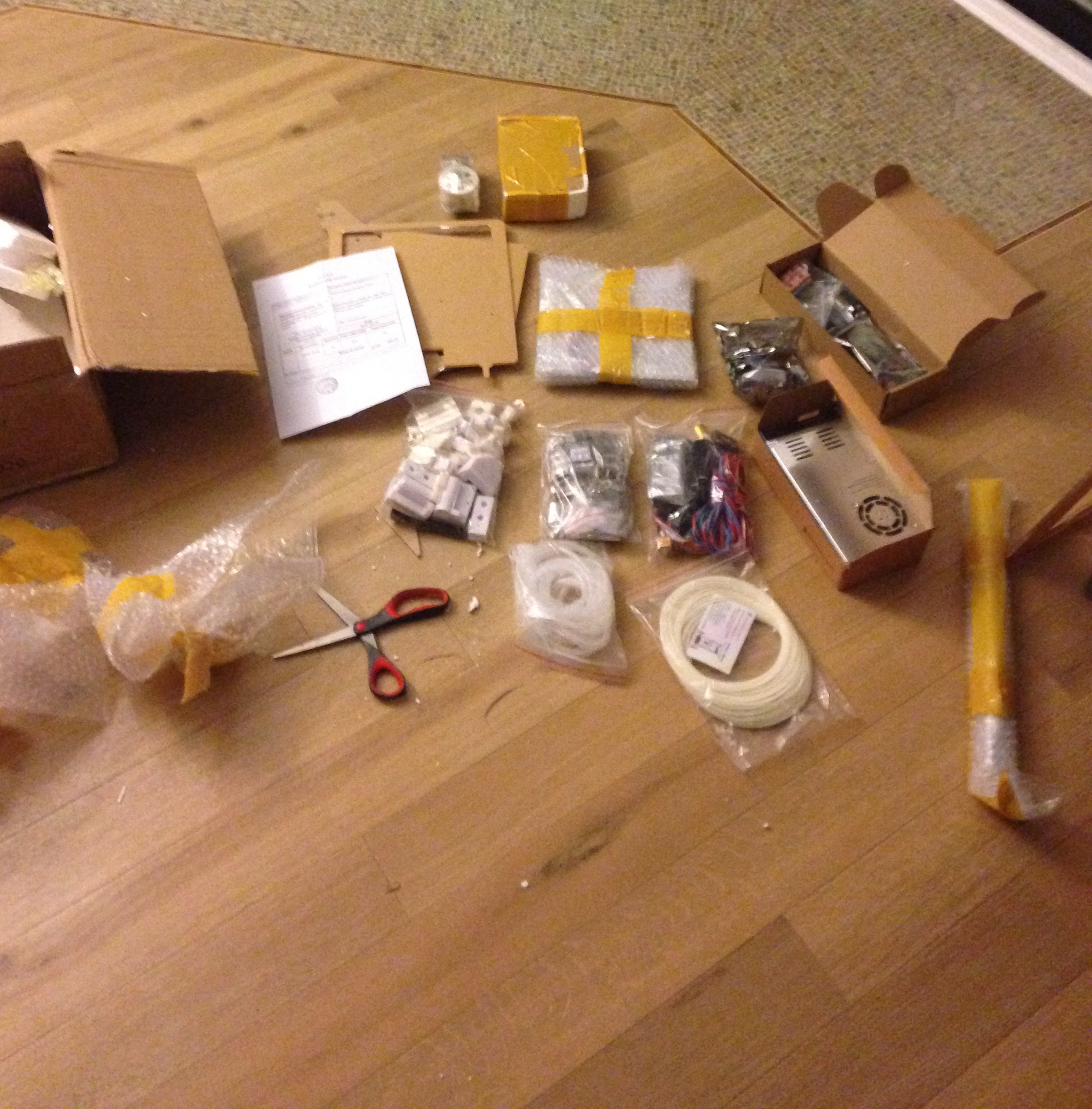
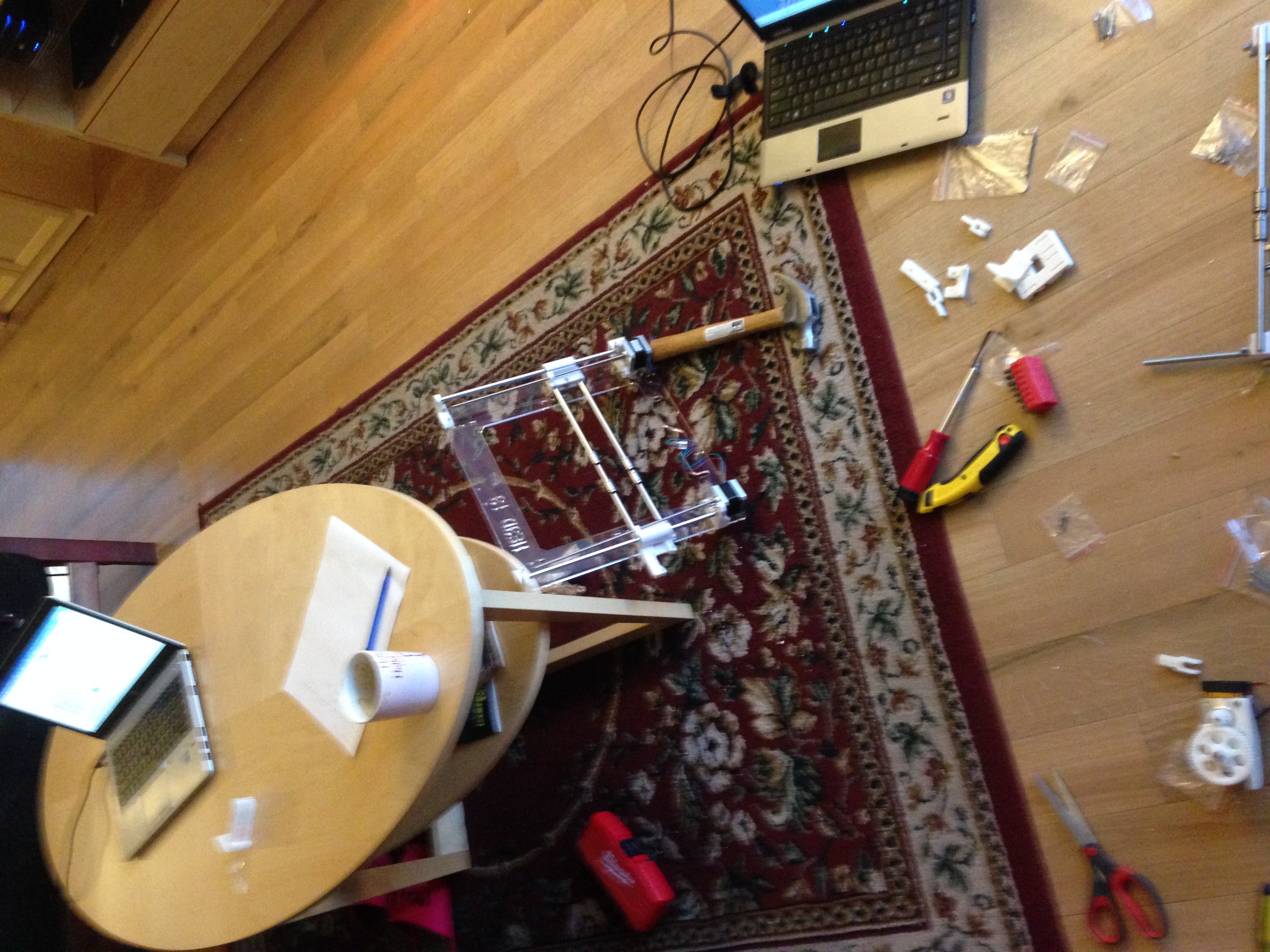
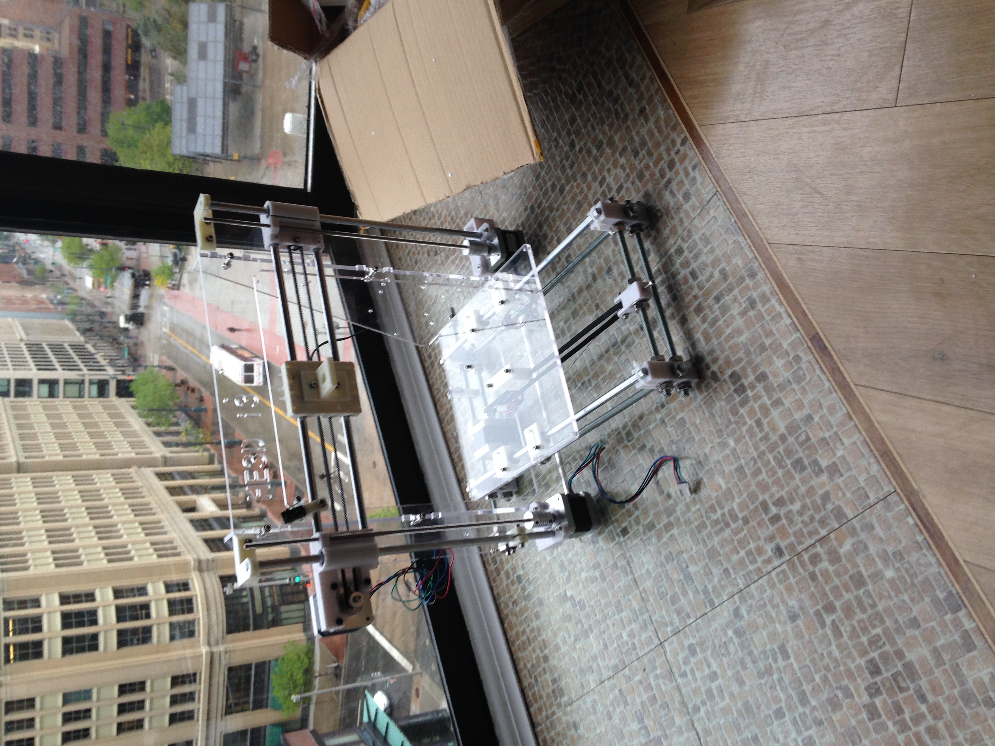
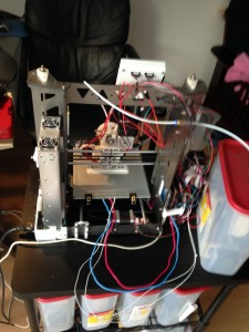
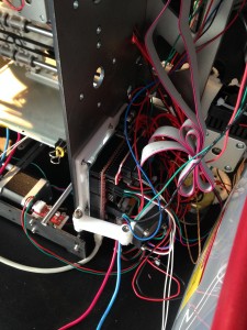
Secondly hitting 153 C on the bed requires a printer without plastic around the bed. I first tried pushing the temp on the bed on my HE3D and totally warped the acrylic that was supporting it. I realized then I needed a printer that didn’t have plastic supporting the bed and also came across the P3Steel design. This laser cut steel frame is really a great solution. It’s all metal between the aluminum heated bed and the smooth rod. If you in the market for a 3D printer with the thought of 3D printing polycarbonate I’d encourage you to go for a P3Steel.  I built mine from scratch but you can also get a reasonably priced kit Oballo Printing for ~$500. Looking back I wished I did this instead of the HE3D i3 kit for $360, although I have learned a lot along the way.

all metal between bed and frame
P3Steel is all metal between the heated bed and the y-axis chassis. First plastic part is under chassis. Frame won’t deform under 150 deg C temperatures.

We need power: Low Resistance (1.6 Ω) Bed, 24 V electronics, and 700 W power supply, relay or FET upgraded ramps

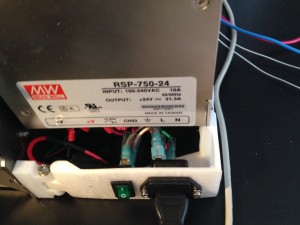
A metal frame will allow you to get to 153 C without your bed bending. You still need the power. I stumbled upon this solution. I ordered my MK3 heated bed from Aliexpress and it came in with a resistance of 1.6 Ω on the 24 V connection which is much lower than typical. This overdrew my 350 W power supply and caused the 24 output to wander around between 20 and 24 V. It was operational but the temp was unstable since my bed was consuming 360 Watts alone. I tried being cheap and getting 700 W PSUs from aliexpress but they appeared to be underpowered and voltage still fluctuated. Ultimately I shelled out the $170 for a MeanWell from mouser and it’s been stable holding at 24 V throughout the print. This low resistance bed means it takes about 2 minutes to bring it up to ~153 deg C.

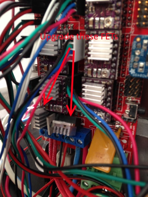
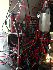
Also stock RAMPS FETs (STP55NOpL) have on resistance on rsistance of 23 mΩ. That may seem small but will cause them to burn switching this much current I’ve done it. They need to be upgraded. I changed them out for 2  IRLB3034PBF-ND with 1.4 mΩ on resistance which was suggest on the forums. On top of this I have a heat sink and cooling. Be careful in removing the old FETS and don’t rip the traces. You could also use the stock FETs to switch a relay but I think it’s just simpler to upgrade them. I’ve read some distributors are selling RAMPs with upgraded fets installed.

Upgrade These Fets
Upgrade these 2 FETs for lower on resistance.

Hitting 330 Deg C on the hot end

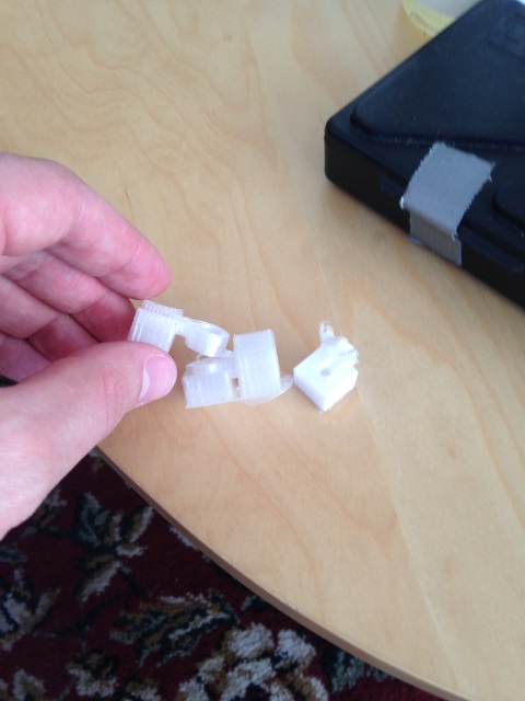
and I’d like got even hotter. I’ve found I can extrude at lower temperatures but I end up with poor layer adhesion that is easily delaminated (shown bellow). The Prometheus hotend I’m printing has .3 mm orifice seems to like to extrude a bit hotter ABS @ 250 Deg C instead of 240. Still I am extruding well over 300 Deg C.

Delamination
Print at .25 mm layers with 315 deg C on hot end easily delaminates. Hotter exterusion prevents delamination.

You probably should upgrade the driving FET for the hot end to a IRL3034PBF like described for the bed and indicated in the picture.

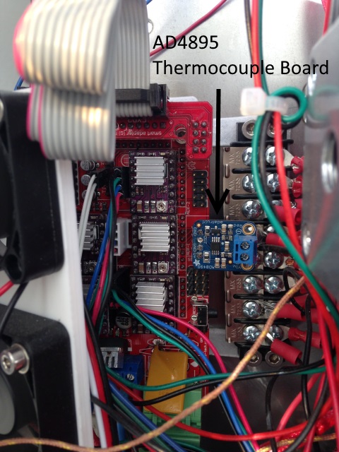
In addition thermistors top out at ~300 C, so a thermocouple is needed on the hotend. I am using and would recommend this AD4895 thermocuple board from Adafruit with k-thermocouple from them too.  I first tried a AD597 Ultimaker Temperature Control Board K Thermocouple Signal Amplifier TC1 from Ebay and found it’s temperature output to be noisy varying wildly. You can solder a header pin onto the back and it’s pin compatible with RAMPS. Marlin will require you to program the equation into temperature.c .

AD4895 Themocouple board on RAMPS 1.4.

My hotend currently tops out at 330 C. I’d like to go even hotter. I’m on a 40 Watt cartridge from amazon.com and just ordered a 80 W one from ebay.

and a dry box

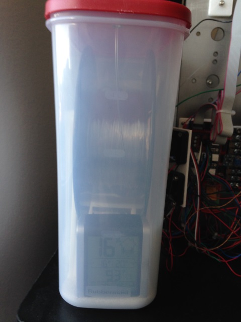
I’ve always had my PC in a dry box. Everything I read said it was needed and I haven’t really tested how things go without it. I haven’t posted the details of my drybox. It’s nothing though special though, there are many designs out there on thingverse. One thing I have done is I put an accurite 006 humidity guage into each box to make sure it’s holding humidity.
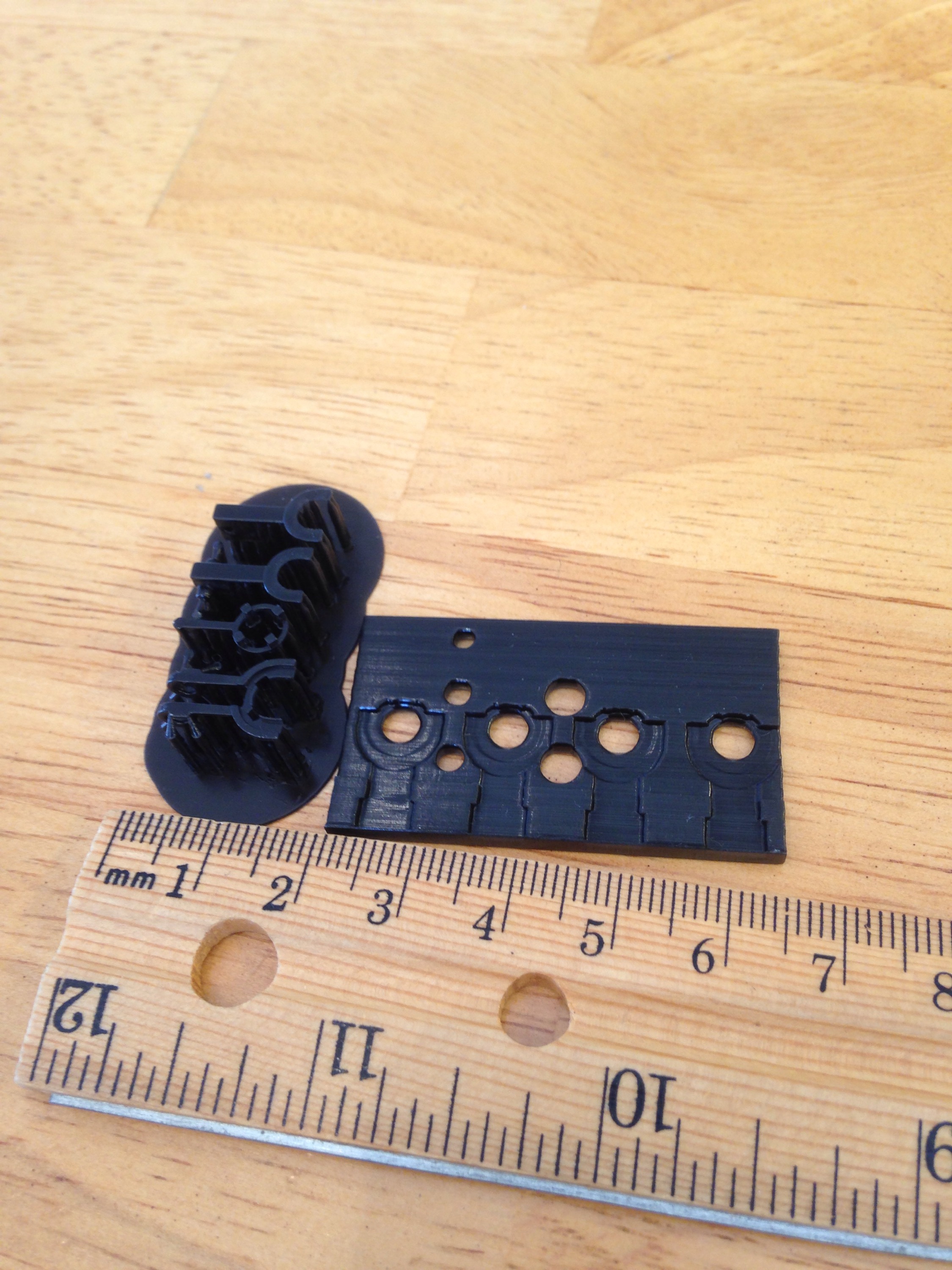
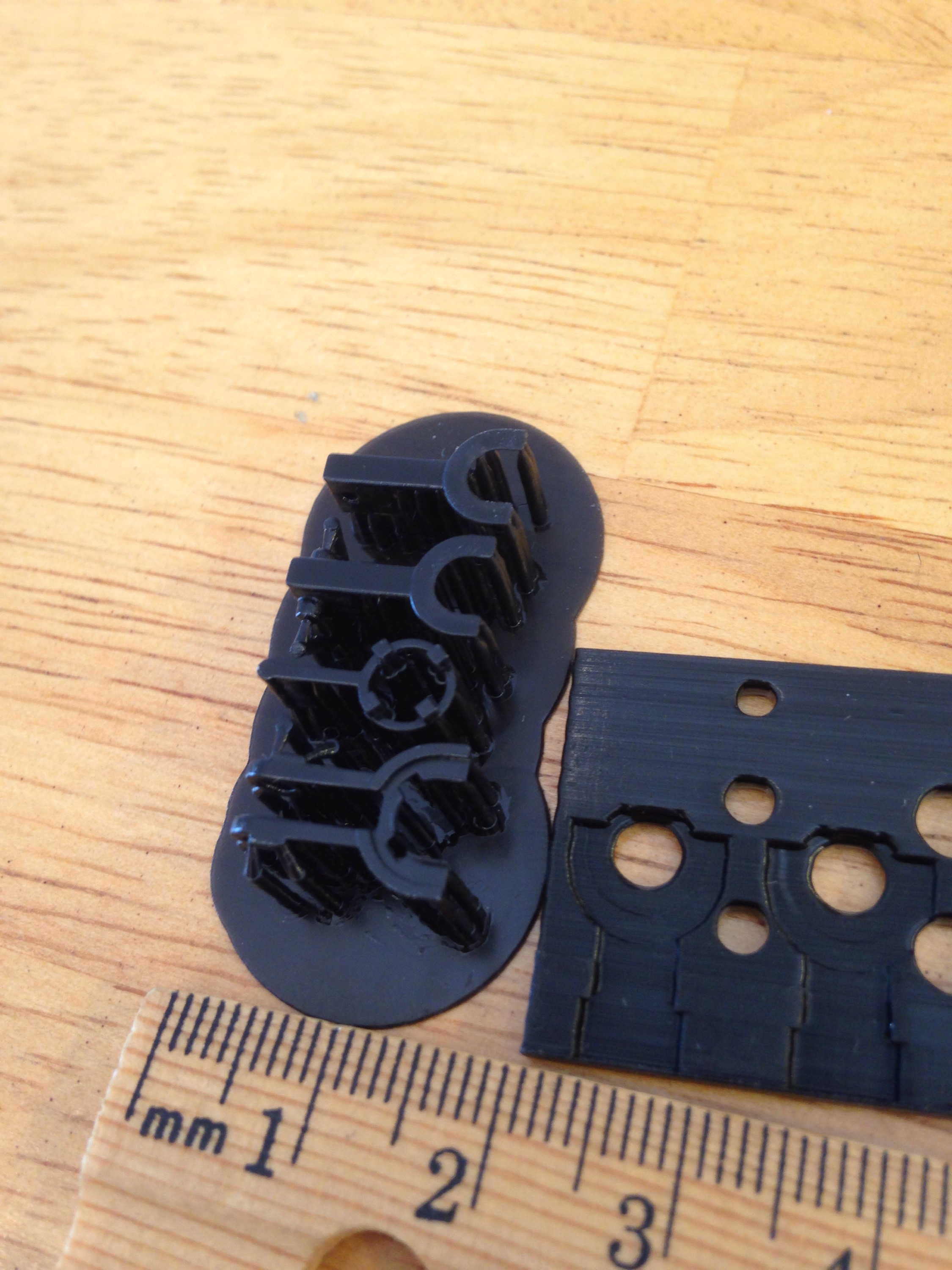
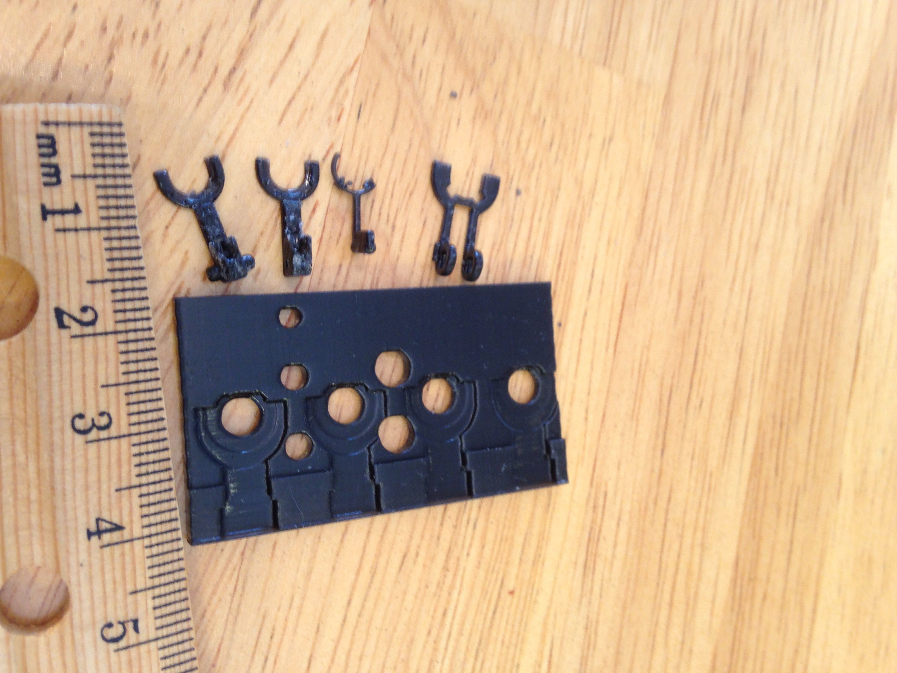
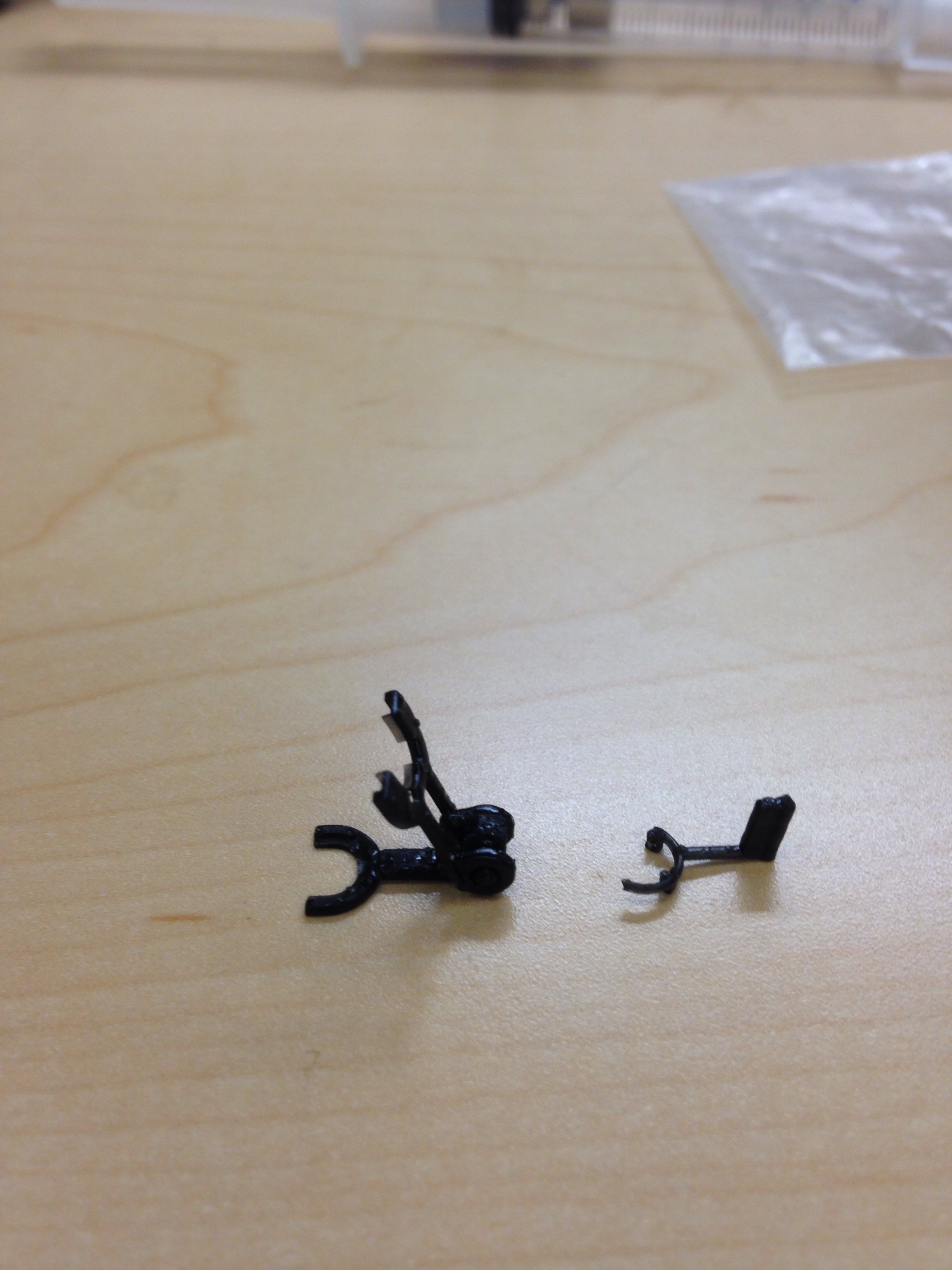
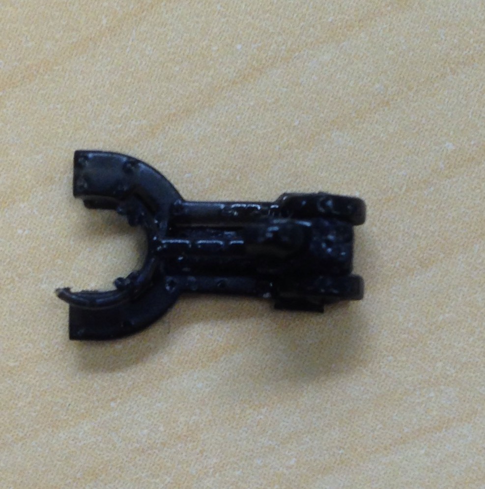
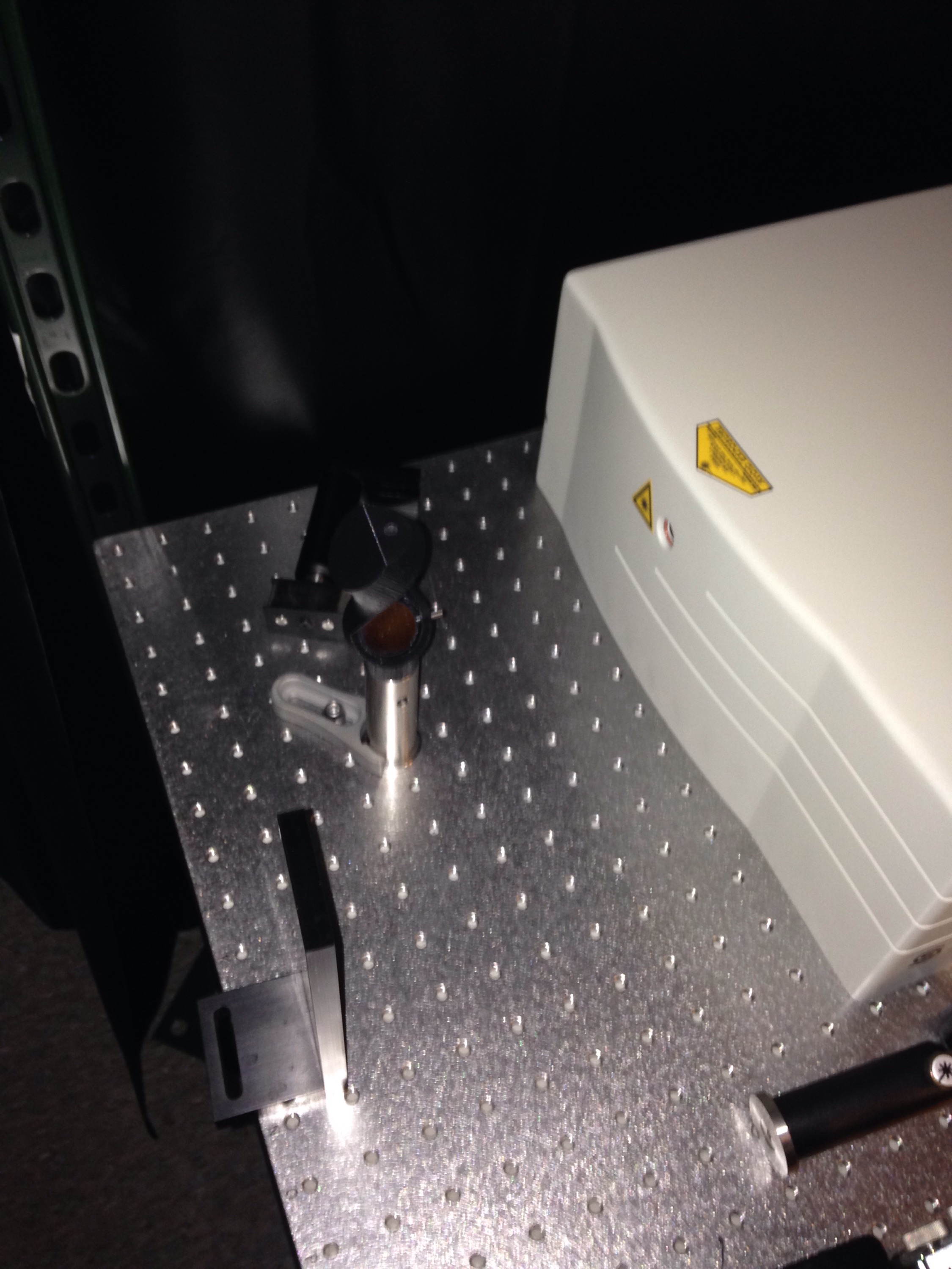
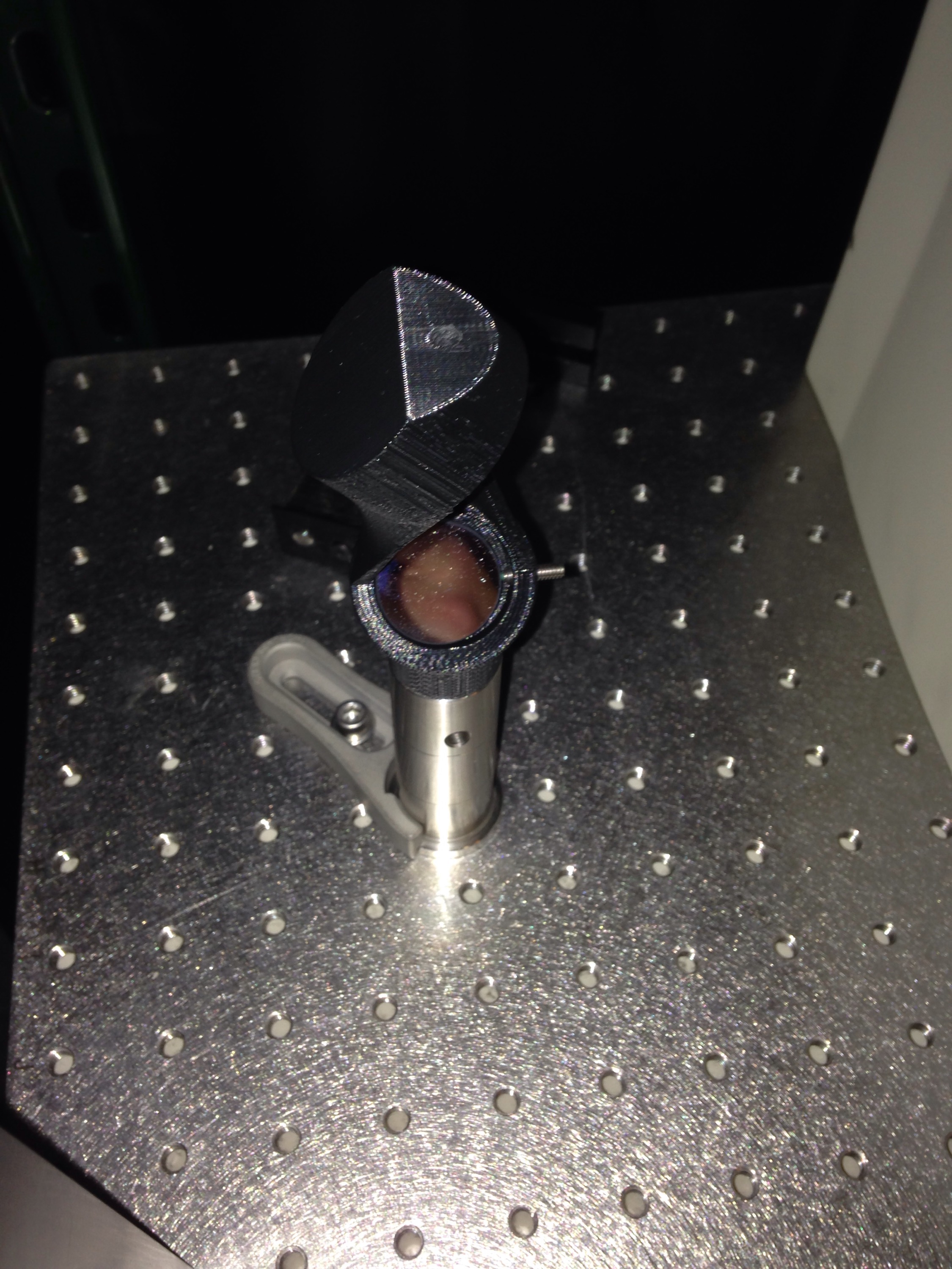
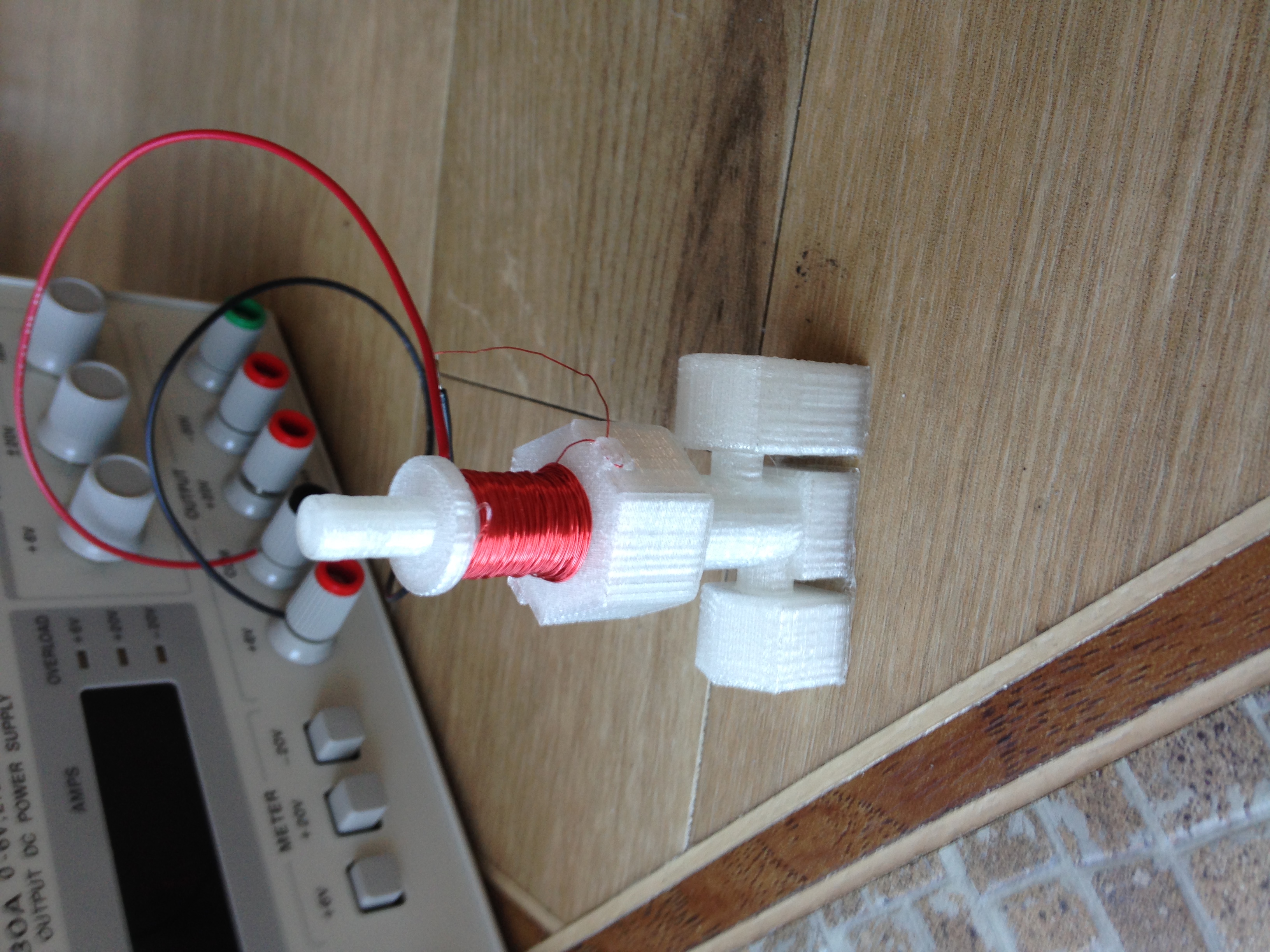
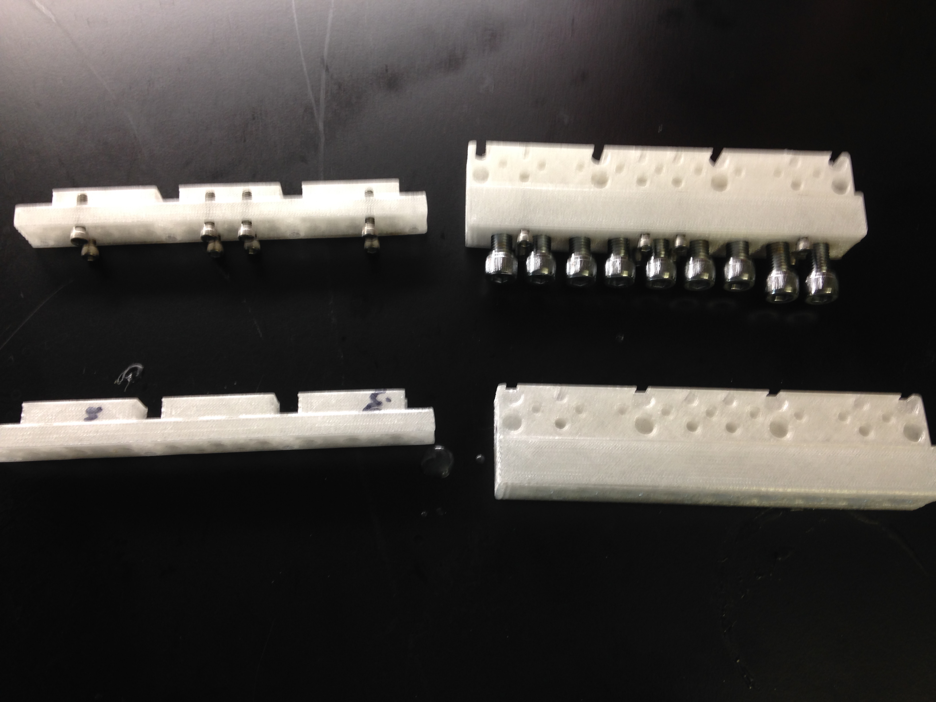
Drybox Image
Dry box containing silicate gel and humidity gauge

Pics of Results

That’s my guide to getting good prints in polycarbonate. Here are some pictures of some parts I’ve printed. If you look at my twitter feed you can see that I’ve also already experimented with sealing these parts with resin based epoxy. I’ll post more on that later. I’ve done more than these few but they are what I can easily find on my phone.

Maybe next I’ll try even more high temp compatible materials like PEEK and Ultem.

Assembled Valve.
Assembled Valve. Top and bottom printed in polycarbonate.
Manifolds for sealing
Manifolds for experiment in sealing with BJB TC-1614. These are fairly big parts those are 1/4″-28 SHC on the right part.

My #CanServe idea for Cancer Moonshot: Engineer Virus Targeting Cells with TP53 Dysfunction

Twitter told me OSA, AACR, and NCI retweeted Biden this morning about the cancer moonshot.

I put up an idea, “Engineering Virus Targeting Cells with TP53 dysfunction” that I wanted further describe here. If this is of interest to you, or you have expertise, please comment on it with that moonshot post. You can login to that site with social media accounts, I used twitter.

In taking cancer biology few years back, among other onco & tumor suppressor genes, I learned about a gene called TP53. This tumor suppressor gene said to be mutated in between 50-100% of all cancers.  cBioportal.org confirms this and can provide you with mutational data from multiple genetic studies. If you type in tp53 this bears out in the results

cBioPortal results for TP53 searched in all studies on June 29, 2016.
cBioPortal results for TP53 searched in all studies on June 29, 2016. Look how high that prevalence is

Even if this is overstated and it’s 50% it seems to be important. My idea there is to design a virus that attacks cells with mutations to TP53. A properly designed virus will be destroyed by healthy cells with a functional TP53 pathway while unhealthy cells with dysfunctional TP53 will allow the virus to replicate.

The Idea

The idea is to use Cre-Lox recombination to make this virus this. Cre-Lox is a recombination technology similar to crisper. Use TP53 as the activator of Cre. As in Cre will only be transcribed in cells with functional TP53. Then put lox positions in the virus such that Cre activation destroys it. Then only cells that have a functional TP53 transcript can destroy the virus. The virus will also transcribe genes activating the apoptotic pathway under an strong promoter. Ideas there bax, or caspases. Strong promoters might be those of Actin or those in other viruses like SV40.

Here is my blueprint of this virus.

Blue print of oncolytic virus targeting cells with TP53 mutations
Blue print of oncolytic virus targeting cells with TP53 mutations. Lox positions are inserted between promoters and genes that lead to virus promotion. Transcription of Cre leads to clevage of viral DNA at lox position.

Anyways, a lot to work out there. There has been some similar work done. It is called Onyx-015. There the HPV virus was mutated to obtain a similar goal. The HPV virus is thought to cause cancer partially though inhibition of TP53 thought he protein E6.

More Background:

TP53 is a transcription factor. It transcribes genes that put an halt on mitosis. Many viruses inhibit TP53 in order to take over the cellular machinery and replicate.

TP53 tetramerizes, as in 4 sub protein units come together upon its activation. Units cane come transcripts from one of 2 copies each person has. Mutations to just one of these alles can lead to this gene to fail to tetramerize and active. Mutations are most likely found in the DNA binding and tetramerization domains of the protein.

Many oncogenes lead to the tetramerization of TP53.  Under normal conditions, TP53 then suppresses growth in these cells to prevent cell proliferation. Hence it is a tumor suppressor gene.

P3Steel 2.5.1. Build

I got my first comment on this blog today. It was on the P3Steel page so I thought it’s about time to post an update. I posted about building a P3Steel with some design modifications back in August of last year. I’ve been waiting to get my build done and performing adequately to post about it. My design modifications for the to 2.5 frame to 2.5.1 are here. This is post is mostly pictures of my assembled version. I put more more information about the parts and proteins used in the build as a separate page.

If you remember from my last post, the deficiencies of the HE3D reprap design is it’s flimsy and wobbles. It’s also difficult to get everything square. Hence laser cutting it all out of 3 mm, I used 11 guage steel by H & H Metals in Colorado. This version is indeed way more rigid in fact it’s completely stiff. Here are some pictures of my build.

P3Steel 2.5.1 Front View

You can see I have it clamped to the cart. I did this to reduce noise and to keep it from slowly walking itself off the front.

Back View of P3Steel 2.5.1. It's on a cart so I can move it around the apartment.
Back View of P3Steel 2.5.1. It’s on a cart so I can move it around the apartment. The red containers are dry boxes for the filament

Some of my changes in 2.5.1 were adding mount points for the Arduinio/Ramps 1.4 electronics. I didn’t get the hole spacing correct so I had to print a plate to interface it. On that plate I added connections for a fan for cooling them and off of it a terminal block for DC power distribution.

IMG_2019
Side View of Arduino/Ramps mounting. Added holes to frame for these electronics to mount to.


IMG_2020
Front view of electronics. I’ve added a terminal block to the right to screw +/- 24 connections into. I thinked it helped make the DC wiring more straight forward.Do you see the thermocouple interface board?

I designed the frame to accommodate a 3 M4 screws for a 350 watt power supply. 350 watts wasn’t enough for my build because of a build plate from aliexpress with just 1.6 Ohm resistance. \frac{(24 \, V)^2}{1.6 \, \Omega} = 360 \, Watts would use my entire PSU. I did it any way and just suffered power fluctuations as when the bed was on the PSU was at 21 volts. So I increased wattage to 700 watts to more than compensate.

Mounting of 700 Watt power supply unit

I designed a bracket to attach the AC input and a switch to. It flips open to give access to the power supply terminals.

IMG_2021
Mounting plate for the power supply unit.

Now to put together the parts list so others can replicate it and derive from it.

Building my $355 Prusa i3 3D Printer

May 9th, so about 3 weeks ago I bought a 3D printer kit with the intention of learning about how the technology works and intending to modify it into a automated pipetting robot for my CTC experiments. I came across this idea after learning about the RepRap project that created open source 3D printing technology and hearing about a OpenTrons that’s trying to do this on a commercial scale. However, I know for my experiments I will need to do more than pipetting so I need to modify the hardware and electronics. I came to the conclusion that the Prusa i3 had become a pretty popular design in the RepRap community and can be purchased in a kit form available on-line.

In searching, I came across 3dprintersonlinestore.com that seems to be the best site out there with reviews of 3D printer kits. Amazon.com has some reviews but their prices and selection aren’t as good and they don’t have a categorical view to see all the models in. If you look at at kits, you’ll notice even though they all claim to be Prusa i3 designs each kit has modifications to it in various ways. For example, many have changed the threaded rod terminating the y-axis carriage to plates. I decided to go with the design that looked most like the open i3 designs, (there are a few i3 designs, rework, Einstein) with the threaded rod thinking it would be easier to modify. So I purchased the He3D i3 for $265 + $90 shipping from China. The rest of this post is about the story of putting it together and getting it to print over the last few weekends. It rained I believe every day of May so it was a good project while staying indoors.

So the box arrived the Thursday after placing the order. The included invoice claimed it as 12 metal stents. There were no instructions included but instructions to e-mail them for instructions.

Unpacked Package

invoice pic

message

Kit Parts More Unpacked.

I didn’t notice the letter on how to get instructions until the 2nd day I spent putting it together. The first day I spent trying to do it from i3 assembly videos on you tube in which there are many series. I was able to get the y-axis partially built in the first day but it was clear this design had its specifics that I needed the videos for. I e-mailed them the 2nd day and they replied with links to the videos (12 in all) and other files (circuit diagram, USB driver, test file, slicer configuration) within a few hours. The videos were very helpful for doing the mechanical assembly but not really useful for the wiring but there the circuit diagram really helped and so did looking up the RAMPS circuit diagrams online which it was pretty much identical too. After the first day, I had the y carriage and x-y axis assembled. With the videos, by the end of Sunday, I had mechanical axises together.

Image of X-Z axis after 1st day didn't get one of Y.
Image of X-Z axis after 1st day didn’t get a pic of the Y- carriage.
Full full mechanical assembly by end of the weekend. You can see the wet weather we've been having.
Full mechanical assembly by end of the weekend. You can see the wet weather motivating us to work on a 3D printer indoors.

I put the project down during the work week and picked it back up again on Memorial Day weekend to finish the electronics and get it printing. I borrowed a soldering iron from work on Saturday. You can see some of the mess that comes with doing electronics work. I choose to work on the floor vs. on a table so that if I dropped screws they wouldn’t fall to the floor with me having to search for 10 minutes to find them again. My legs, particularly knees, got a little sore working on the floor but maybe that’s a good thing.

Electronics Mess

When I got to the end of the electronics I decided I should take a picture of all the tools + supplies I used to get to this point so I could put it up here. It’s not too many. You don’t need to have two drill bit sets for example you just need 4 bits but they’re metric (more accessible to the rest of the world but not me in Denver) and harder to get a hold of. You could get by without a soldering iron by using crimps instead.

Tools to Build
Tools I used to assemble the 3D printer. You may be able to get by with less tools.


I got the electronics together late in the evening. I smelled something weird (magic smoke leaving electronics) after I powered it up the first day and thought I had burned out the power supply. I looked it over closer the next morning with the digital multimeter (DMM) and found it was fine. I had bridged power to ground accidentally by hooking up one of the end stops wrong (switches so it can sense the end of the end travel) – after swapping it I got it to power up & motors moving. Here is a pic of it making it’s first print by the end of Memorial Day weekend.

IMG_0962

The part is a test of nut cut ins I’ve designed. It was important to test the press fits of the nuts in a servo enclosure for a galvanometer on a laser scanning microscope we are building. Here are the the mechanical design and stl & solid works files if you are interested.

nut cut in test print

Test Print – Nut Cut In – Rotated.STL

Test Print Design.zip – SolidWorks files and pdf of above drawing.

Those measured values aren’t what I measured on my print though. It came out undersized. Those are the values I measured of this print on a Lulzbot Taz 5 that we setup a weeks ago at work. That assembly only took a few hours vs. 2 weekends for this one but I learned a lot more. I still need to tune the Configuration.h parameters (here is my current Configuration.h 2 weeks better than the one I used here)  for my printer I almost surely don’t have the right value for steps per mm set in Marlin. As I’m two weeks removed from this now but have still been working on it, I have gotten better printers and actually know a few things that still need to be done but I’ll put that up in my next post. Here is how that test print looked in comparison to off the Lulzbot Taz 5 at work. This post is getting kinda long so more to come on tweaks and tuning.

The print off my Prusa i3 He3D (white) compared to the Lulzbot Taz 5 black.

Latest prints of small parts 

I posted this yesterday and posted them via my phone while I as freeing the parts from the support structure. Now I’m going through the pictures to reinsert them into wordpress so their not so big and add some descriptions. Clicking on them will still produce full resolution. These parts were printed at the 3dprintingstore (Denver, Co) on a B9 Creator.

Parts before removal of support structure
Here are the parts before I removed them from the support structure.
A zoomed in view of the smaller parts before removal.

I used small clippers to cut them free. Perhaps I needed to be a little more careful as I ended up cracking the o-ring remover. Here here is pictures of the parts cut free.

Picture of parts cut free
Picture of parts cut free. Some damage occurred to the o-ring remover. It’s hard to get the clippers underneath the piece and remove without flexing the material.  to the o-ring remover. The parts on the left are similar with one having the post for a hinge the other with a though to put a 0-80 set screw into.

The hinge between the spatula and clamper worked as in it swings around the hinge! (1st time). Here is a pic of that and the dimensions that worked.

Pic of clamper mounted on spatula. Hinge worked.

Here’s a drawing of how it looked in cad. I had to make the tolerance between the parts 300 um to get it to be able to move.

Hinge
Drawing of hinge. It took 300 um tolerance between the axle attached to the spatula and the through hole attached to the Clamper to get the hindge to move. Previous attempt was under toleranced. The 1.524 mm is the OD of a 0-80 set screw.

The dove tail redesign worked as well. Here is a look at pics of it sliding into the filter spatula.

Filter remover inserted into the spatula. Dove Tail 2.0 design successful.
Filter remover inserted into the spatula. You can barely see the inserted part because of poor contrast between black on black materials.

Here is the drawing of that feature with tolerances. They were expanded since previous print

Drawing of Dove Tail 2.0 Design. 2.0 isn't really a dove tail because it's circular in structure but achieves the same goal.
Drawing of Dove Tail 2.0 Design. 2.0 isn’t really a dove tail because it’s circular in structure but achieves the same goal.

I still have 2 features that didn’t work that are the notch on the plate and the teeth of the o-ring remover. The plate also came back slightly undersized.


Measured size of feature on plate
Actual dimension width is larger than measured.

Notes from PJ Simpson-Haidaris & Stephen C. Ekker’s talk on how to write F Award

I had the opportunity to attend a talk on the keys to write a F grant at the Translational Science 2014 meeting in DC. I’m transcribing my notes here to put them in a place that will be more lasting for me. i.e. instead of the folder with all the other meeting notes that’s going to get buried under other papers.

The talk was by PJ. Simpson-Haidaris, Ph.DStephen C. Ekker, Ph.D.  Dr. Simpson-Haidaris kindly uploaded the slide deck to slide share (link to slide deck on slideshare). Dr. Simpson-Haidaris is an expert on this subject and has has served on over 80+ grant review panels (qualifications on slide 4 of her deck).

My notes:

  • F grants require exceptional mentoring teams
  • If you don’t have a research and career development plan (IDP) you should work on getting one together. Templates vary between universities in terms of usefulness. Dr. Simpson-Haidaris recommends the Vanderbilt template (link) .
  • Dr. Ekker stated that a retrospective study of failed applications showed that half of them failed because they didn’t follow the rules.
  • Now can use 200 character title in unicode for longer more descriptive project titles. You may get dinged if your title comes through the system truncated or with misinformed characters.
  • Use the SF424 as a checklist.
  • Dr. Simpson-Haidaris finds biosketches most important. Makes sure they are correct and up to date for allowed participants. Make sure biosketches includes PMCID#s.
  • A F award must go above and beyond the PhD and post doc training the applicant would otherwise participate in or receive.
  • There was some disagreement between Drs. Ekker & Simpson-Haidaris on the definition of “key personal” vs. “senior personal”. Dr. Ekker asserted it is a administrative term and only those that will be administrating the grant should be named. He used the criteria of if this person gets hit by a bus will this grant need to end. He pointed out this definition is for protection you if your PI leaves your institution or has medical issues you don’t lose your funding too. He stated that all others are “senior” rather than “key” personal. Dr. Simpson-Haidaris took the view of these peoples roles on the project in the scientific sense. Still not sure what right answer is here.
  • Typical grant consists of sponsor + co-sponsor + 2 more mentors specific to the project.
  • Check eRA commons account before applying. Status needs to be PI instead of trainee before submission.
  • Can go down to 8 pt font size for figures.
  • Explain any gaps in productivity.
  • Make sure to include PMCID#s in all work cited if they exist. Failure to do this can cause the grant to be thrown out.

Notes from Robert J. Freishtat talk on how to Write RO1

Here are some notes I took down Friday April 17, 2015 from Robert J. Freishtat talk on how to write an RO1 at Translational Science 2015 in DC. The it was a good talk that lasted 1.5 hours.

    • Average Age for R01 is 42 years old for those with PhD 45, for those with MD-PhD.
    • Subscribe to the NIH Guide List Serve. Comes out every Friday and tells about new funding opportunities. (My Note: You can also follow @NIHFunding on twitter)
    • Know what PAS, PAR, RFA mean and how they are different.
      • PAS – Program Announcement with set aside funding.
      • PAR – Program with dedicated review committee
    • Read the program announcement 5 times.
      • NIH may change instructions without notice so check close to submission to make sure nothing has changed
    • Collaborators & Co-Investigators are more important for new investigator
    • Check eRA commons to make sure you have “new investigator” at the bottom of your login if you in fact are one. Work with your university to adjust if incorrect.
    • Early Investigator is 10 year from terminal degree.
    • When applying with Multi-PI R01 oldest investigator trumps new investigator title. Be careful if you are looking to use the new investigator mechanism.
    • Support Structure & Resources as consultants on teams with “street cred.” speaks volumes
    • For 1st R01, due to lack of record, potential is important. Want to see learning and improving

Reach out to program officer early in process. They can and often want to help you.


Components of a “Good Grant”:

1. Sections

  • Brief introduction
  • Background to establish solid foundation
  • The goal of the app.
  • The central hypothesis
  • Rationale for project
  • Specific Aims
  • Anticipated Results

2. General ideas

  • Don’t let the reviewers think. If one sentence leads the reader to think of something the next sentence must answer that.
  • Make it easy to fill in the review document.  R01 Review Template 2015.04.22
  • Make the team strong. What about the team makes it better than one with an identical application on the same topic.
  • You only need one area to drive the impact score.
  • Convince the reviewer (hopefully 1st reviewer) to be champion of grant
  • know what NIH funds. Use projectreporter.nih.gov
  • Get assigned to multiple institutes
  • Use a cover letter and specify desired institute and study section there.
  • Capture imagination in 1st page
  • 2/3 – 1 pg about significance. (Can do bullets here)
  • Cite articles of reviewers expected to be on study section if possible.
  • Every sentence counts.
  • Approach structured like aims.
  • Sell yourself & the team in the 1st paragraph of the approach section.
  • Any point you want to reviewer to remember needs to be repeated 3 times in the grant. It’s a rule from marketing.
  • Preliminary studies don’t have be “studies”
  • Talk about data collection: instruments and assays
  • Do a sample size/power calculation (common place for criticism)
  • Close with timeline at end.
  • Talk about limitations
  • Turn off the thesaurus and reuse words.
  • Keep the scope small… Junior investigators especially tend to over shoot.
  • Last paragraph like a manuscript abstract. Think of it like a book. The parts of a book that get read with the most attention are first and last pages.

It’s clear to me this was a very informative talk so I spent the few minutes to transcribe my notes to some place more durable i.e. here.

3D Printed Periscope

I designed and a periscope to change the beam height from a Mai-Tai laser which comes out at 5.41″ (where did they get that # from to 4″) . The design was done in solid works and was based around 1″ mirrors from thorlabs. I dimensioned the part around the mirror model I downloaded from Thorlabs after I mated them in an assembly. Here are some pics of the printed part on the table. I’ll try to upload the solid works and stl files later when I’m back at my pc in a few days.


I had it printed at the 3D printing store. More to come.


So here is some drawings and CAD files for the periscope.

periscope side view

Here is a drawing of the side view. The idea was that by adjusting the plane 1 offset it would allow the distance between to be configurable. Unfortunately, height configuration though adjustment of Plane 1 position didn’t work in this version. I checked it after printing what I needed and saw, when the plane 1 position changes the position of the mirrors change but the position of the circular holders doesn’t move. I played with it a little but wasn’t able to fix it. I’ll spend more time on it when I need another periscope. In the meantime, if this model might be useful you can down load it in the .zip file below.

Files:

Periscope STL File , Solid Works Files: Periscope Project 1650.zip